Skip to content
Synafloat
Book a call
In a call we clarify whether the simulation answers your parameter question.

Simulation software for laser DED with wire or powder

Causes of varying bead height

Even along a straight toolpath, heat and melt flow change. Bead height can therefore vary while the parameters stay fixed.

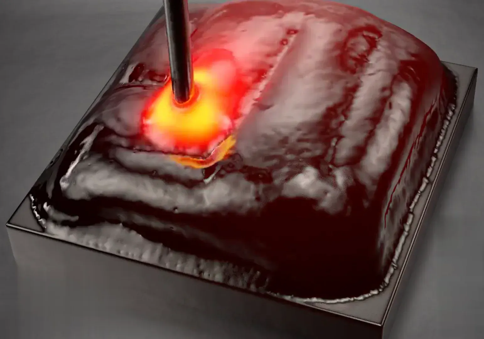
A multi-layer laser DED build in the simulation.

Fixed parameters, changing conditions

While laser power, travel speed and material feed stay the same along a straight toolpath, the surrounding material changes as the build progresses.

Parameters and melt-pool physics

A machine log records the commanded parameters but not the melt pool that formed with them. A bead-scale melt-pool model represents local heat and melt flow and explains how bead height can vary as the build grows.

A constant bead height therefore needs parameters that change along the toolpath.

Three influencing factors

Schematic, illustration

Toolpath geometrySchematic in section: a thin wall, one bead wide, turns at a corner. There is air on both sides of the wall. The melt pool sits in the corner. Two arrows show that heat can only flow away into the two legs of the wall.
Accumulated heatSchematic in side view: solidified layers lie on top of each other, and the top one is being deposited. The melt pool sits at its front end. A single arrow shows that little heat flows into the already warm part.
Local heat sinkSchematic in cross-section, two cases: in the first, the melt pool sits next to a freshly deposited bead, and two arrows show heat flowing into the substrate. In the second, it sits on bare substrate, and three arrows show more heat flowing away.

Three factors set how much heat flows away from the moving melt pool and so change the local bead geometry.

Toolpath geometry
A corner, an overhang or a change in wall thickness sets how much surrounding material conducts heat away from the melt pool.
Accumulated heat
At constant laser power the part heats up more with every additional layer, because heat flow is limited and heat accumulates in the part.
Local heat sink
Freshly deposited material next to a bead conducts heat differently from the substrate. This difference sets how quickly the melt pool solidifies next to the bead.
Three factors, schematic

Limits of this explanation

This explanation covers bead height and melt depth but does not establish the mechanical state inside the finished part.

Related pages

  • The model behind this explanation

    The method page describes the bead-scale melt-pool model this explanation draws on.

    How the method works
  • The applications of the software

    The case “Thin wall, many layers” shows how the software adapts the parameters layer by layer.

    See the applications
  • Melt-pool simulation with or without a mesh

    The comparison shows how both approaches represent the moving surface.

    Melt-pool simulation with or without a mesh

Let’s talk about your part

In a call we clarify whether the simulation answers your parameter question.

Book a call

You pick the slot on book.synafloat.com.

Enquiry via the contact form

You talk to Dr. Michael BlankThe founder has researched particle-based melt-pool simulation since 2017 and earned his doctorate in the field.

For the first call

  • A short, non-confidential outline of your part and question
  • Machine, material, wire or powder

In the pilot project, per enquiry

  • Matching the simulation with your experiments
  • Parameter strategies for the whole toolpath
  • Adjusted machine file

Funding

EXIST – from science to business
Funded by the EXIST Business Start-up Grant at the FAPS institute of FAU, funding period 09/2025 to 08/2026.
FAU – Friedrich-Alexander-Universität Erlangen-NürnbergFAPS – Institute for Factory Automation and Production Systems, FAU

Partner: Friedrich-Alexander-Universität Erlangen-Nürnberg (FAU). Synafloat is a spin-off of FAU.

ESA BIC Northern Germany

Incubated at the ESA Business Incubation Centre in Bremen since November 2026.