Skip to content
Synafloat
Book a call
In a call we clarify whether the simulation answers your parameter question.

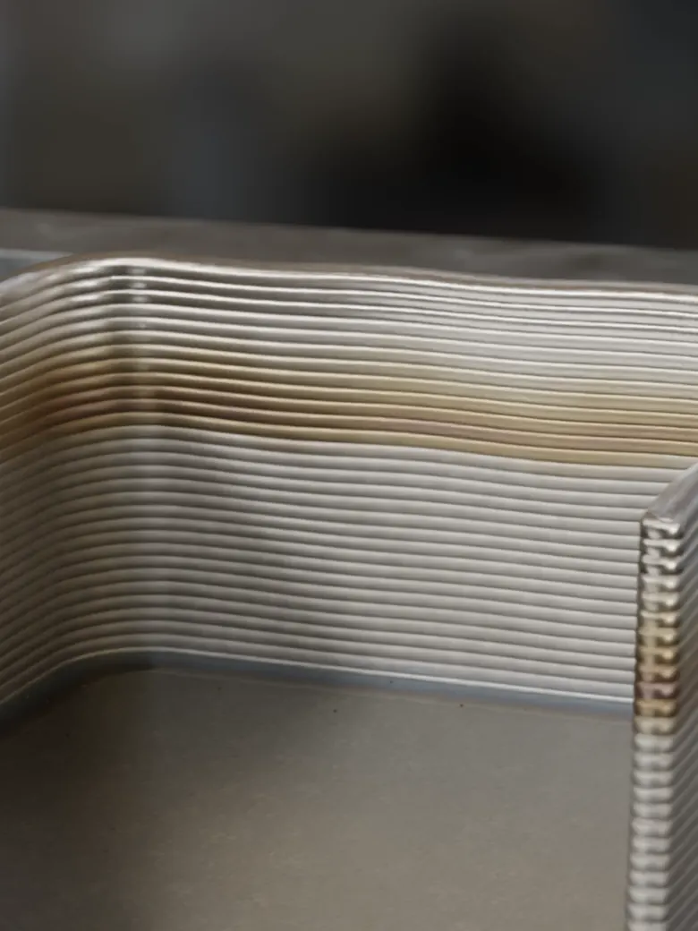
Silent animation without text: a wall is built layer by layer, first with wavy layers, then evenly.

Simulation software for laser DED with wire or powder

DED parameters for new parts, repair and coating

Simulate. Optimize. Print.

The software adapts laser power, travel speed and material feed layer by layer and writes them into your machine file. Your team checks the file before the print.

Synafloat in 30 seconds

Silent animation: a part built with a fixed parameter set and with adjusted parameters, compared.
Synafloat platform: 3D view with a robot arm and laser DED head above the build plate.

Platform, screenshot

The platform is in development. We are happy to talk about a pilot project for your process, or you can register your interest in platform access.

Platform: in development

Six applications

Laser DED parameters are still determined in elaborate physical prints, for each material and each geometry.

Thin wall, many layers

Build a wall over many layers while heat accumulates.
Goal: constant layer height over 40 minutes of build time.

Laser power640–1620W6001,2001,8006401620decreases as the part heats upWire feed5.8–12.6mm/s510155.812.6rises because the accumulated heatcan melt more wire010203040 minLaser power640–1620Wdecreases as the part heats up6001,2001,8006401620Wire feed5.8–12.6mm/srises because the accumulated heatcan melt more wire510155.812.602040 minLaser power640–1620W6001,2001,8006401620Wire feed5.8–12.6mm/s510155.812.602040 min

Laser power stays between 640 and 1620 W over 40 minutes and decreases as the part heats up. Wire feed stays between 5.8 and 12.6 mm/s and rises because the accumulated heat can melt more wire.
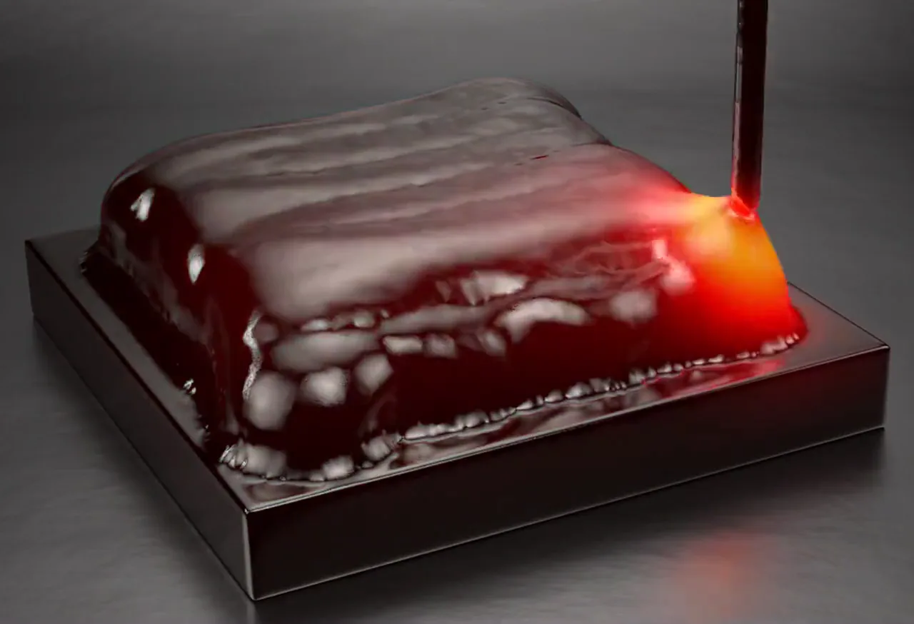
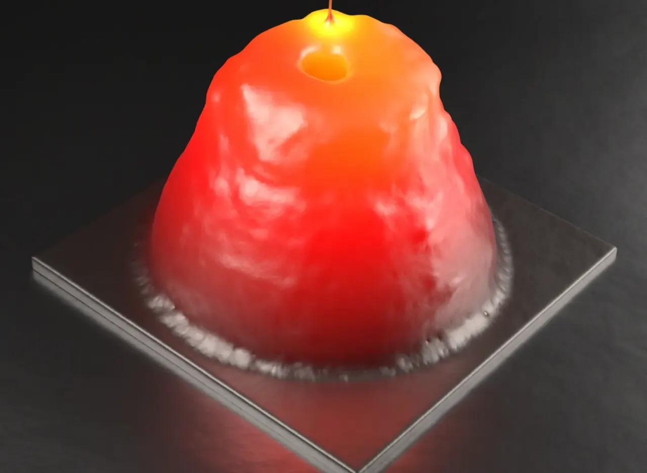
Cone demonstrator, wire. Clip and curves from the same run.

New part

Develop parameters for a new geometry.

Because the layer height drifts with a fixed parameter set, the software adjusts the parameter set layer by layer.

The layer height drifts and the build becomes unstable.

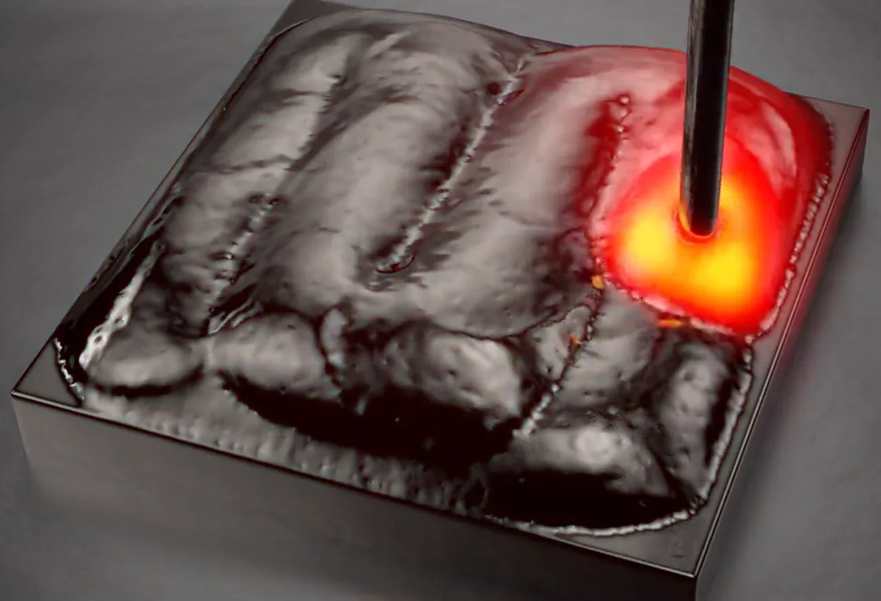
Cube demonstrator, fixed parameter set

The layer height stays constant.

Cube demonstrator, adjusted parameter set

The overhang on the right comes from the undersized base plate in the model and is not a process defect.

Four more applications

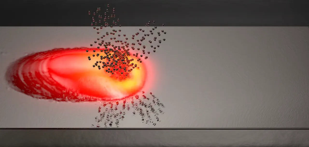
With powder
  • Coating

    Apply a functional layer across the surface, bead beside bead.

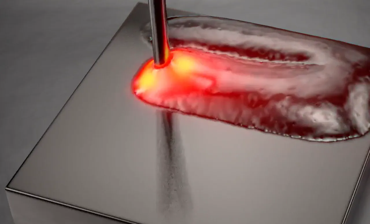
    With wire

  • Build-up on an existing part

    Build new geometry onto an existing part.

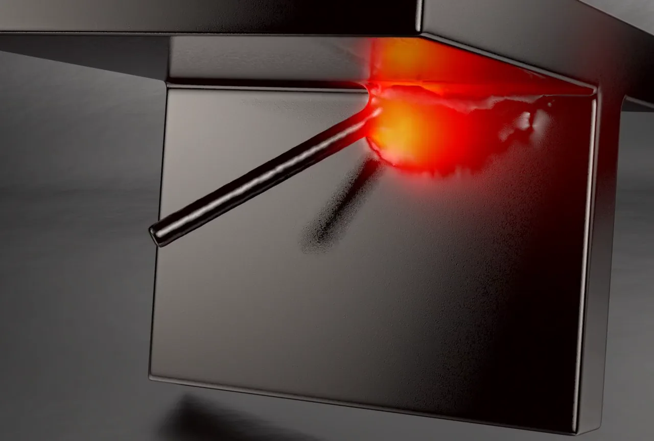
    With wire

  • A bead deposited overhead under a horizontal plate

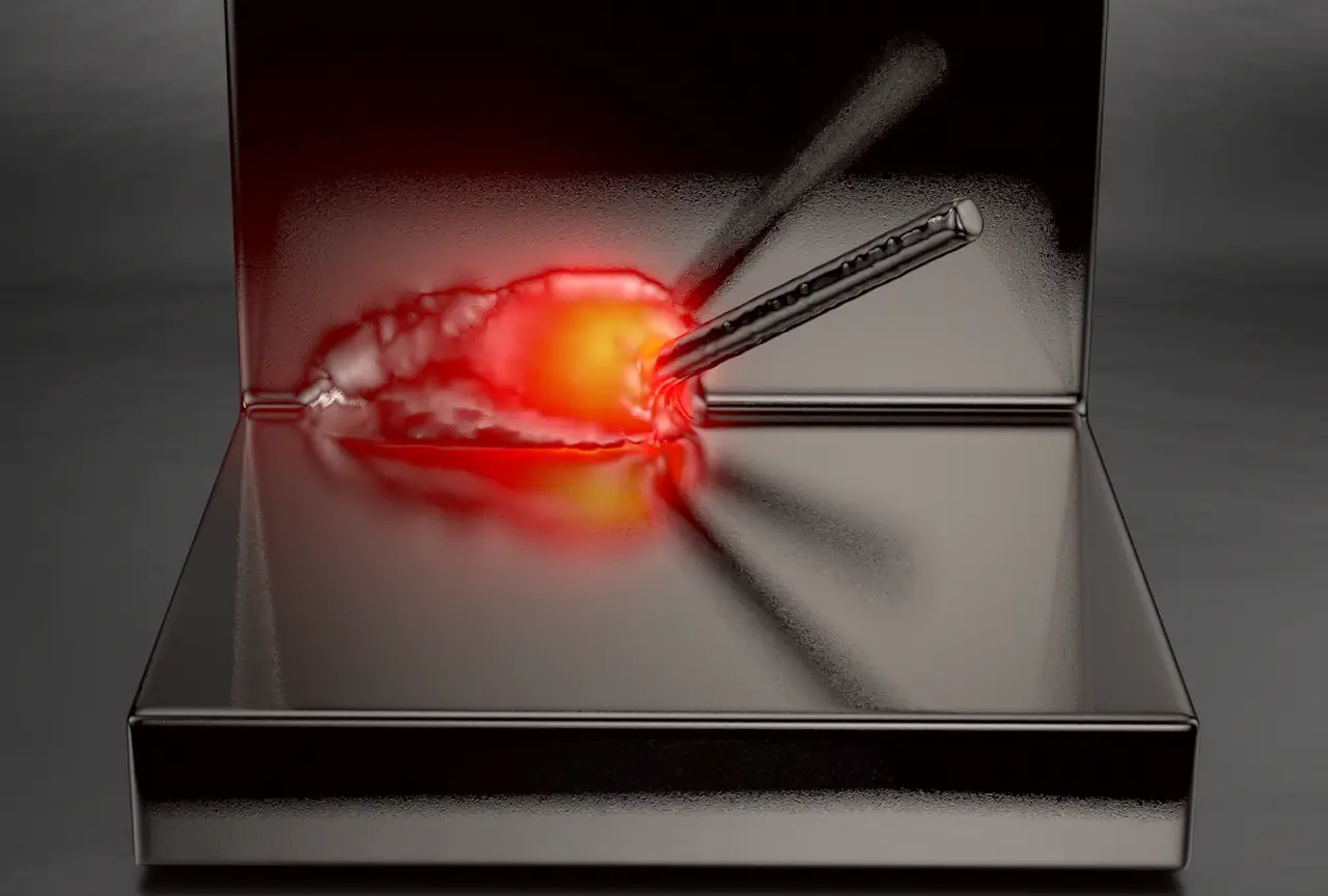
    Overhangs, inclined walls

    A wall at an incline, each layer offset sideways.

    With wire

  • Repair, schematicSection through a part with a worn edge. Two beads fill the notch layer by layer, a third is being deposited. Dashed: the original contour.

    Schematic, illustration

    Deposition onto an existing part, schematic

    Repair

    Rebuild a worn contour on the part.

Handover

Your team receives the machine file with adjusted process parameters, checks it before the print and uses it for further process development.

matched
Pure titanium with single-track experiments, founder’s doctoral thesis, 2023 (external)
open
Your material: matched only with a measured bead

Mesh-free simulation

Instead of a computational mesh, freely moving particles (SPH) represent the melt. This lets us simulate whole toolpaths, up to whole parts, in one run.

With a computational mesh
With free particles (Synafloat)

A moving computational mesh has to be adapted to the growing part; the particles follow the material.

Your pilot project

In a pilot project we calibrate the simulation to experimental results from your machine. We set the scope per enquiry.

You talk to Dr. Michael BlankThe founder has researched particle-based melt-pool simulation since 2017 and earned his doctorate in the field.

In a call we clarify whether the simulation answers your parameter question.

Funding

EXIST – from science to business
Funded by the EXIST Business Start-up Grant at the FAPS institute of FAU, funding period 09/2025 to 08/2026.
FAU – Friedrich-Alexander-Universität Erlangen-NürnbergFAPS – Institute for Factory Automation and Production Systems, FAU

Partner: Friedrich-Alexander-Universität Erlangen-Nürnberg (FAU). Synafloat is a spin-off of FAU.

ESA BIC Northern Germany

Incubated at the ESA Business Incubation Centre in Bremen since November 2026.